как вы чувствуйете когда видете Это видео
Thứ Ba, 31 tháng 5, 2011
Thứ Hai, 30 tháng 5, 2011
 00:19
00:19 Unknown
 Revit Arch
 No comments
In Revit there are two distinct schedule types, “Building Components” and “Key” schedules.

Building Component Schedules
These are the default schedule types, each object instance will appear in the schedule by default.
Key Schedules
Best used to setup a number of standard “styles” for an object type. Each row of data in the Key Schedule will create a new style to apply to an object. Once applied, the style will pre-fill all fields as needed. This setup is ideal where there are numerous standard types, and you don’t need every instance of the object to appear in a schedule. I have included a short video below on this process:
Video Example
A few items to keep in mind:
1. Key Schedules cannot utilize Shared Parameters for a field; “Project Parameters” are only available in this schedule type.
2. To combine “Keys”, “Project Parameters” and “Shared Parameters” in a schedule, use a “Building Components” schedule type. I have included a short video below on this process:
Video Example
I hope this information is helpful to better explain the two schedule types.
Source: revitclinic.typepad.com
Chủ Nhật, 29 tháng 5, 2011
 19:15
19:15 Unknown
 Revit Arch
 No comments
Sau loạt bài về tạo xà gồ, đòn tay, mái tôn trong Revit, hôm nay mời các bạn thưởng thức mái ngói gốm trong Revit.
Để tạo được mái ngói như các ngôi nhà Việt Nam một cách thật nhất bằng mô hình chứ không phải bằng ảnh Texture, mời các bạn tham khảo bài của tôi vừa viết. Qua bài này, chúng ta thấy khả năng của Revit là rất lớn, chỉ có điều chúng ta có khai thác hết được không mà thôi.
Để tạo được mái ngói như các ngôi nhà Việt Nam một cách thật nhất bằng mô hình chứ không phải bằng ảnh Texture, mời các bạn tham khảo bài của tôi vừa viết. Qua bài này, chúng ta thấy khả năng của Revit là rất lớn, chỉ có điều chúng ta có khai thác hết được không mà thôi.
Thứ Bảy, 28 tháng 5, 2011
Thứ Sáu, 27 tháng 5, 2011
 17:20
17:20 Unknown
 Revit Arch
 No comments
I am frequently asked about the keynoting feature in Autodesk Revit; how to use it and how to set it up. It’s actually quite simple, and with a little bit of effort can reward you with a much-simplified annotation system, whether you actually use keynotes (reference or sheet) or simply want standardized “typical” text notes.
The following tutorial will attempt to walk through the process of using keynotes. Then we’ll take a look at how to customize them. This tutorial will use the standard keynotes file that ships with Revit Architecture (as well as Revit Structure and Revit MEP).
Associating the Keynotes File
Before you can use the keynoting feature in Revit, you must first associate your project with a keynotes file. You can do this in your template project if you want to use an office standard keynotes file, or you can use a separate file for each project.
To associate a keynotes file, go to Settings->Keynoting. The first item in the dialog is the path to your keynotes file. Note in the figure below that it is currently reflecting the default keynotes file, which should be located in your Imperial or Metric Library. This is a simple text file which can be edited or created from scratch, as we will see later.
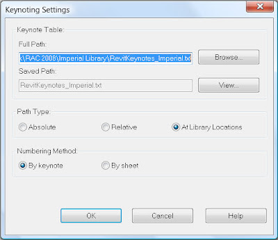
Figure 1 – the Keynotes Settings dialog
Note the other settings in the keynotes file. Most importantly we will discuss the difference between the numbering methods “By sheet” and “By keynote” later.
Assigning Keynotes to Materials and Types
Once you’ve associated the keynotes file to your project or template you can begin to assign keynotes to material definitions and element types. Note in figure 2 and 3 that both the Material Definitions dialog (on the “Identity” tab) and the Type properties of any element have a field for a Keynote to be assigned.
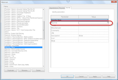
Figure 2 – the Material Definitions dialog, with the “Identity” tab selected.
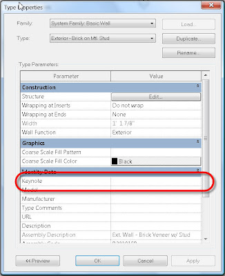
Figure 3 – the Type Properties dialog of a wall type.
Additionally, the Family Types dialog of a component family definition will allow the assignment of a keynote to any component or detail component family. Selecting the browse button in the Keynote field in any of these dialogs will take you to the associated keynote file, allowing you to select from any of your standard notes. Figure 4 shows the default Imperial keynote file, which is structured around the 16 division CSI format.
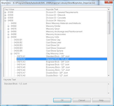
Figure 4 – The default Imperial keynotes file.
So, now you’ve associated a keynotes file to your project and you’ve assigned keynotes to your materials and type definitions. The hard part is done.
Using Keynotes
To use keynotes, go to the drafting panel and select the “Keynote” tool. You have three options:
Element: Pick an element and the keynote assigned to the type definition will be used.
Material: Pick an element that has materials assigned to its components and the keynote assigned to the material definition will be used.
User: Pick any element. Whether or not it already has a keynote assigned to it you will be taken to the keynotes file to select any other keynote that you prefer to use.
If you select an element or material that has no keynote assigned to it yet, you’ll also be sent to the keynotes file to select a note. Once selected, that keynote will then be assigned to the element or material that you selected for future picks. If you accidentally select the wrong keynote during this process, you need to edit the type (or material definition) properties and change the keynote assignment there.
Referring back to the keynotes settings dialog box shown in Figure 1 again, note that you can choose to use “By sheet ” or “By keynote” when you place keynotes. The difference between these is simple but significant. “By sheet” refers to a system where each keynote is assigned a number that is unique on a particular sheet, however the same keynote could be a different number on a different sheet. Typically the numbers will simply be “1”, “2”, etc. “By keynote” is a system where the actual keynote number specified in the keynotes file will be used, and will be consistent for a given keynote across all sheets. The terms “By sheet” and “By keynote” refer to the US National CAD Standard “Sheet Keynotes” and “Reference Keynotes”, respectively. Figure 5 shows a detail annotated with the “By keynote” (reference keynotes) option. Figure 6 shows the same detail annotated with the “By sheet” (sheet keynotes) option.
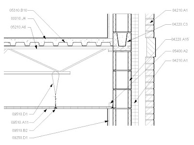
Figure 5 – A detail annotated with the “By keynote” option.
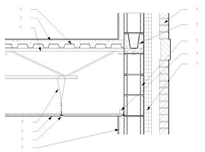
Figure 6 – A detail annotated with the “By sheet” option.
Note that with the sheet keynotes, the actual keynote number is not assigned; instead there is a simple “?” placeholder. The number will be assigned when the detail is actually placed on a sheet. You can actually switch an entire project’s details from the reference keynotes option to the sheet keynotes option by simply switching the choice in the Keynotes Settings dialog. All existing keynotes in your project will update immediately to the new system.
Keynotes are essentially nothing more than tags. You can choose to use a tag definition that displays the keynote number, or you can choose to use one that displays the keynote text itself. Therefore, even if you don’t use keynoting as an annotation method, you can still use this feature in Revit to standardize and automate your text annotation.
Creating Keynote Legends
Keynote legends are nothing more than a schedule view. To create them, however, you need to go to the View pull down menu and select New->Keynote Legend; you won’t find the option on the View design bar. Once the legend is created, you’ll see it listed in the Project Browser with the rest of your schedules.
Viewing the properties of the legend, you’ll see, in fact, that it has the same structure as any other Revit schedule with one critical exception. On the “Filter” tab there will be an option at the bottom to allow you to filter keynotes by sheet, as in figure 7.
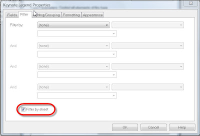
Figure 7 – filtering keynotes by sheet.
Turning this option on will allow you to have all of your keynotes in one keynote legend. However you can use the legend on multiple sheets. For each sheet that you place it on, only those keynotes that appear on the sheet will be shown in the legend. If you are using sheet keynotes, the keynote number will be blank in the legend view, since each one can vary from sheet to sheet, but when the legend is placed on the various sheets the numbers for those sheets will be assigned.
That’s it. That’s all there is to working with keynotes. The critical thing to make it move fluidly and quickly is to take the time to assign keynotes to all of your component family types and system family types, as well as your material definitions. This means that you will probably also need to either edit the default keynotes text file or create a new one. Read on…
Customizing a Keynote File
Although keynote files are nothing more than simple text (.txt) files, the best tool to use to create or edit them is actually a spreadsheet editor such as Microsoft Excel. The formatting is a little ugly in the raw text form, but much more readable in spreadsheet form. When you open the file in Excel (we’ll use the default Imperial keynotes file as an example), make sure to set the file type in the File Open dialog to “all” so that you can see .txt files. After selecting the file, choose the “Delimited” option in the Text Import Wizard, and select “Next”. In the next screen, select “Tab” as the delimiter; you should see a preview of the file in the same dialog box.
Once the file is opened in Excel, you should notice that there are three columns. The first column is the actual keynote number for each note (or the section header for a group of keynotes). The second column is the keynote itself or the header text. The third column is a reference section – it is the section number that the keynote in that row falls under. This is how the keynote file can appear to “cascade” in the keynote dialog box. Looking at figure 8, let’s examine this a bit closer.
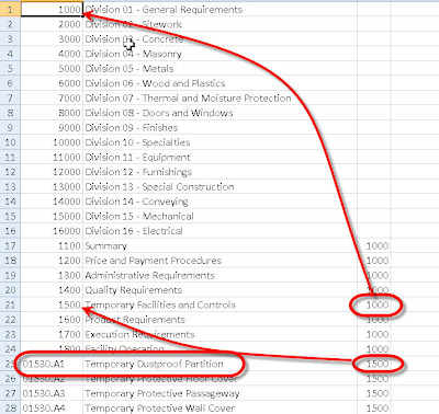
Figure 8 – a partial view of the default Imperial keynote text file
Notice the entry for “01530.A1”. The keynote text for that entry will be “Temporary Dustproof Partition”. It will fall under the section 1500 – “Temporary Facilities and Controls” – note the reference to section 1500 in the far right column for the keynote. Section 1500 will, in turn, fall underneath Section 1000, “Division 01 – General Requirements”, because it’s far right column includes a reference to that section. Rows that do not include a reference in the far right column will be considered top-level headers.
It’s that simple. After editing the file, make sure you save it back to .txt format, not .xls, and you’re ready to go!
That’s all there is to Revit keynoting – create/modify your keynote file, associate it to your project or template, assign keynotes to your type and material definitions, and start annotating!
By modocrmadt.blogspot.com
The following tutorial will attempt to walk through the process of using keynotes. Then we’ll take a look at how to customize them. This tutorial will use the standard keynotes file that ships with Revit Architecture (as well as Revit Structure and Revit MEP).
Associating the Keynotes File
Before you can use the keynoting feature in Revit, you must first associate your project with a keynotes file. You can do this in your template project if you want to use an office standard keynotes file, or you can use a separate file for each project.
To associate a keynotes file, go to Settings->Keynoting. The first item in the dialog is the path to your keynotes file. Note in the figure below that it is currently reflecting the default keynotes file, which should be located in your Imperial or Metric Library. This is a simple text file which can be edited or created from scratch, as we will see later.

Figure 1 – the Keynotes Settings dialog
Note the other settings in the keynotes file. Most importantly we will discuss the difference between the numbering methods “By sheet” and “By keynote” later.
Assigning Keynotes to Materials and Types
Once you’ve associated the keynotes file to your project or template you can begin to assign keynotes to material definitions and element types. Note in figure 2 and 3 that both the Material Definitions dialog (on the “Identity” tab) and the Type properties of any element have a field for a Keynote to be assigned.

Figure 2 – the Material Definitions dialog, with the “Identity” tab selected.

Figure 3 – the Type Properties dialog of a wall type.
Additionally, the Family Types dialog of a component family definition will allow the assignment of a keynote to any component or detail component family. Selecting the browse button in the Keynote field in any of these dialogs will take you to the associated keynote file, allowing you to select from any of your standard notes. Figure 4 shows the default Imperial keynote file, which is structured around the 16 division CSI format.

Figure 4 – The default Imperial keynotes file.
So, now you’ve associated a keynotes file to your project and you’ve assigned keynotes to your materials and type definitions. The hard part is done.
Using Keynotes
To use keynotes, go to the drafting panel and select the “Keynote” tool. You have three options:
Element: Pick an element and the keynote assigned to the type definition will be used.
Material: Pick an element that has materials assigned to its components and the keynote assigned to the material definition will be used.
User: Pick any element. Whether or not it already has a keynote assigned to it you will be taken to the keynotes file to select any other keynote that you prefer to use.
If you select an element or material that has no keynote assigned to it yet, you’ll also be sent to the keynotes file to select a note. Once selected, that keynote will then be assigned to the element or material that you selected for future picks. If you accidentally select the wrong keynote during this process, you need to edit the type (or material definition) properties and change the keynote assignment there.
Referring back to the keynotes settings dialog box shown in Figure 1 again, note that you can choose to use “By sheet ” or “By keynote” when you place keynotes. The difference between these is simple but significant. “By sheet” refers to a system where each keynote is assigned a number that is unique on a particular sheet, however the same keynote could be a different number on a different sheet. Typically the numbers will simply be “1”, “2”, etc. “By keynote” is a system where the actual keynote number specified in the keynotes file will be used, and will be consistent for a given keynote across all sheets. The terms “By sheet” and “By keynote” refer to the US National CAD Standard “Sheet Keynotes” and “Reference Keynotes”, respectively. Figure 5 shows a detail annotated with the “By keynote” (reference keynotes) option. Figure 6 shows the same detail annotated with the “By sheet” (sheet keynotes) option.

Figure 5 – A detail annotated with the “By keynote” option.

Figure 6 – A detail annotated with the “By sheet” option.
Note that with the sheet keynotes, the actual keynote number is not assigned; instead there is a simple “?” placeholder. The number will be assigned when the detail is actually placed on a sheet. You can actually switch an entire project’s details from the reference keynotes option to the sheet keynotes option by simply switching the choice in the Keynotes Settings dialog. All existing keynotes in your project will update immediately to the new system.
Keynotes are essentially nothing more than tags. You can choose to use a tag definition that displays the keynote number, or you can choose to use one that displays the keynote text itself. Therefore, even if you don’t use keynoting as an annotation method, you can still use this feature in Revit to standardize and automate your text annotation.
Creating Keynote Legends
Keynote legends are nothing more than a schedule view. To create them, however, you need to go to the View pull down menu and select New->Keynote Legend; you won’t find the option on the View design bar. Once the legend is created, you’ll see it listed in the Project Browser with the rest of your schedules.
Viewing the properties of the legend, you’ll see, in fact, that it has the same structure as any other Revit schedule with one critical exception. On the “Filter” tab there will be an option at the bottom to allow you to filter keynotes by sheet, as in figure 7.

Figure 7 – filtering keynotes by sheet.
Turning this option on will allow you to have all of your keynotes in one keynote legend. However you can use the legend on multiple sheets. For each sheet that you place it on, only those keynotes that appear on the sheet will be shown in the legend. If you are using sheet keynotes, the keynote number will be blank in the legend view, since each one can vary from sheet to sheet, but when the legend is placed on the various sheets the numbers for those sheets will be assigned.
That’s it. That’s all there is to working with keynotes. The critical thing to make it move fluidly and quickly is to take the time to assign keynotes to all of your component family types and system family types, as well as your material definitions. This means that you will probably also need to either edit the default keynotes text file or create a new one. Read on…
Customizing a Keynote File
Although keynote files are nothing more than simple text (.txt) files, the best tool to use to create or edit them is actually a spreadsheet editor such as Microsoft Excel. The formatting is a little ugly in the raw text form, but much more readable in spreadsheet form. When you open the file in Excel (we’ll use the default Imperial keynotes file as an example), make sure to set the file type in the File Open dialog to “all” so that you can see .txt files. After selecting the file, choose the “Delimited” option in the Text Import Wizard, and select “Next”. In the next screen, select “Tab” as the delimiter; you should see a preview of the file in the same dialog box.
Once the file is opened in Excel, you should notice that there are three columns. The first column is the actual keynote number for each note (or the section header for a group of keynotes). The second column is the keynote itself or the header text. The third column is a reference section – it is the section number that the keynote in that row falls under. This is how the keynote file can appear to “cascade” in the keynote dialog box. Looking at figure 8, let’s examine this a bit closer.

Figure 8 – a partial view of the default Imperial keynote text file
Notice the entry for “01530.A1”. The keynote text for that entry will be “Temporary Dustproof Partition”. It will fall under the section 1500 – “Temporary Facilities and Controls” – note the reference to section 1500 in the far right column for the keynote. Section 1500 will, in turn, fall underneath Section 1000, “Division 01 – General Requirements”, because it’s far right column includes a reference to that section. Rows that do not include a reference in the far right column will be considered top-level headers.
It’s that simple. After editing the file, make sure you save it back to .txt format, not .xls, and you’re ready to go!
That’s all there is to Revit keynoting – create/modify your keynote file, associate it to your project or template, assign keynotes to your type and material definitions, and start annotating!
By modocrmadt.blogspot.com
Thứ Năm, 26 tháng 5, 2011
Thứ Tư, 25 tháng 5, 2011
 07:33
07:33 Unknown
 Revit Arch
 No comments

Today Autodesk announced details of the 2012 AEC portfolio and once again this is my yearly roundup / review of the Autodesk Revit Architecture product. Similar to last year, the alpha for this release started particular early, so those involved in this feedback process got a good insight into what was being proposed. In fact when I visited Autodesk last year I go an early preview of some of the work that was taking place. I was fortunate enough to sit in on one of the development meetings where the concept scoping document was being discussed on a particular feature in this release. This was extremely enlightening; my overall opinion was that it was very similar to how the AEC industry works. In our case, we are the clients, we decide what we want and propose this to the researchers (the architect), the researchers then work with the developers (the contractor) to see how best to actually build the design. It is the architect as well as the contractor’s responsibilities to work within the budget constraints and to deliver the product on time. Fair enough, this is a simplistic view on the situation and it is probably not as black and white as what I have described, as there are many factors that could and will disrupt the development process.
So back to the Revit Architecture 2012; I will just be covering the Architectural and major platform enhancements and features; I am sure others will do a better technical review of Structure and MEP improvements than I will do.
So the key highlights include:-

 The managed links dialog also see some minor tweaks. The Revit links tab is now positioned first, Users can now sort the columns by clicking the header of the columns. The default columns sizes have been improved to make reviewing and reading easier. Building on 2011, additional MEP elements categories have been made available to the copy / monitor function.

A new view control bar has been added to each window which allows you to access these new Worksharing graphic features. When you go into a particular mode text in canvas is used to indicate which temporary display mode you are using.
 The tool tip feature has also been expanded providing the user with more Worksharing information as you hover over a particular element; where once you had to wait a fraction of a second for the tool tip to appear it is now instantaneous.
  A major limitation of Revit in previous years has been the inadequate functionality of the edit requests feature. This tool, has from my memory never been improved? Where project teams have been disconnected geographically or just within the office, the use of instant message tools has become the norm to let team members know that you have placed a request or borrow an element or to get someone to relinquish and sync to central. The Worksharing monitor released a few years back did go some way to assist, but it was really on stop gap solution. However, when Revit Server was introduced, you quickly discovered that the Worksharing monitor was not supported in the environment! So it is refreshing to see that Revit 2012 now provides balloon notifications when editing requests. When you receive request, you can use the buttons provided to show the elements that need to be relinquished. No more throwing items at your team members to get them to relinquish borrowed items!
Its pleasing to see that Workset Visibility can now be managed by view templates! Another minor improvement is the introduction of a Starting View. We at HOK along with many other firms, choose to have a starting view. This view in our case is a drafting view which indicates project details and is the neutral view we encourage all our users to save in.
  This ensures that everybody gets the same view when they create a new local copy and experience has shown that this view opens quicker than having to wait for a large 3d view to appear on the screen. Therefore, the new Starting View command allows you to specify which view appears by default when you open the file. Another minor tweak is the ability to change the Workset parameter without first needing to borrow an element.
Finally, the most potentially useful as well as “dangerous” feature is the ability to disable Worksets. This really has been a long standing request, because once Worksetted, officially you were unable to disable Worksets. Technically this is not true, as this functionality has been lurking around in the background for some time, but it has never been exposed to the user. Whilst it will be a very useful feature, without careful and proper management it could spell disaster if it gets into the hands of the Revit novice! Therefore, this feature has been hidden out of the way and has been integrated into the detach from central workflow. When detaching from central you can detach and preserve Worksets or you can detach and discard Worksets which in effect turns it back into a standalone file.
Revit 2012 sees improvements across the board; the export user interface has been updated, pre-sets can be saved once you have configured the output to your requirements. The export settings can be transferred between projects, using the Transfer Project Standards command. Revit 2012 is now able to export style based dimensions; this will ensure that the dimension text is controlled by the text style and the tick mark is controlled by the arrow heads properties; no more proxy graphics to represent dimensions in the DWG export.
 Lines, Patterns, Text and Fonts, Colours, Geometry type, Units can also be customized to a far more granular level of detail. In the case of Lines types you can map Revit to use a .LIN file and Hatch Patterns you can map to a use a .PAT file. All this should help to improve the clarity of DWG exports from Revit. I do hope it will meet most users’ needs, especially where you need to match to existing DWG CAD standards. But I will reiterate, whilst it is a major improvement, you shouldn’t take for granted that this will resolve all your DWG clarity problems, there are some very complex CAD standards out there!
 The Graphic Display Options Dialog box has also gone through a major overhaul. You are now able to create a View Template directly from this reconfigured Dialog. After user feedback from Revit 2011, there are now a number of additional visual styles such as:
 Another sneaky little gem is the ability to print Ambient Occlusion! You will also find the introduction of Ghost Surfaces. This is a new graphic mode which will display surfaces with 30% transparency. This is particularly useful and will provide the user with additional control over complex 3D visualisations. The Ghost Surface feature can be applied to whole view, by category, by element or as a filter. Below you can see the image has had the Ghost Surfaces applied.
 One of the foremost benefits of working in Revit and 3d is the ability to generate assembly 3d views and 3d details. I have said it many times, but give somebody a 3d isometric of an assembly and they will have a better understanding of how the components go together. The guys over at Lego have been doing this for years!!! So Revit 2012 now includes a new 3d view lock feature which allows you to lock to an orientation of a 3d and then tag elements within the view. The user has 3 possible options available; save orientation and lock the view, restore orientation and lock the view, unlock the view. This is control via the View Control Bar.
Whilst I am on the subject of 3d, final Revit 2012 sees 3dconnexion device support. You will need to install the current drivers for you 3dspace mouse, but when you do an appropriate 3dspace mouse icon will appear on the Navigation Bar.
When Autodesk switched to the Ribbon, one rather nice feature in 2010 was the ability to have Type Selector positioned in the Ribbon. Revit 2011 stole us of this feature and the Type Selector migrated its way to the Properties Palette. But I am glade to say the Type Selector in the Ribbon is back. If you right mouse click over the type selector in the Properties Palette you can add it to the QAT (Quick Access Toolbar) as well as the Ribbon.
 Schedule and legends views can now be created directly from the project browser. Just go to Schedule / Quantities or Legends in the Project Browser, right mouse click and choose from the drop down menu.
 Other user experience tweaks include the ability to export Family Types from a Project to a TXT file, import types into a family from TXT file, save all families from a project or a family, customizable equality text, a number of improvements to Dimension Leaders and a new Round Function for Formulas.
As with every release of Revit, Autodesk strive to improve the product performance. Purge Unused now includes unused Imported Categories and Object Styles, loading elements into memory now has multi-threading support. Also Multi-threading has also been extended to the calculation of silhouette edge graphics as well as graphical representation of model elements in open views, when changing view properties of a view.
The workplane Viewer is now available in the project environment and you can now use Adaptive Components in the project environment; you will discover that shape handles have been provided to improve the placement and positioning of AC’s. Although it should be not that there are some restrictions on the use of AC’s, you will only be able to use AC’s in Revit Architecture, no Revit Structure or Revit MEP support for the time being. The creation of surface sub-regions on non-planar surfaces in the Conceptual Environment, which first appeared as part of the subscription drop, has been enhanced further. It is accessible via the Split Face tool in the Geometry panel. This allows you to draw on the surface of non-planar surface and apply different materials to the sub-region using the Paint tool. An essential feature when apply materials to masses for energy analysis exercises.
 A long standing request from the Revit community is to allow families to cut other families. So 2012 now allows face-based void families to be hosted on and cut Structural Framing, Columns, Structural Foundations or Generic model families within the Project. Also, families which just contain voids only and don’t actually cut anything in the family itself can be used to cut walls, floors, roofs, ceilings as well as the family types mentioned previously. This starts to resolve a number of use cases such as holes in beams or the ability to automatically cut an opening in a worktop when placing a sink.

 Parts are produced by breaking down the compound components which make up walls, roofs, ceilings and floors. When you select a wall for instance and choose to create parts, the wall will break down into its individual component layers. The individual parts do retain the geometric relationship with its original element. However, Parts do have their own properties, so they can be scheduled and can be modified independently. By enabling the grip handle functionality available from the properties palette you can pull the various layers around. Once Parts are made, you can then use the Divide Parts Command to divide the compound Part further by using sketch lines on the active workplace.
Assembly and Assembly views have been introduced to resolve certain pre-cast construction workflows. To generate an assembly, you select the elements you want to group as part of your assembly, and then choose the Create Assembly Command. Once you have created the assembly and named it, it will appear under assemblies in the project browser. You can then generate views from the assembly by clicking on the create views commands. This allows you to create shop drawings of components which are independent of the main model. Both these features have massive potential; it will start to allow for more granular detailing. A word of warning though, these feature are only available in Revit Architecture and Structure; when you break your model into parts it will add weight to your model as the original element is still retained. I joked last year when I saw this feature that I could see some going mad and breaking everything and anything without understanding the consequences!
 The other minor improvement is the control of parameter values for points hosted on line or curves. Previous to 2012, whilst you could host a point on a line, the parameter was normalized between a value of 0 to 1. This got even more confusion on circles as the value was expressed in radians. Now you can still express the normalised segmented length between 0 and 1, but you also have additional parameters for segmented length, normalized segment length, chord length, angle, non-normalized curve parameter and normalized curve parameter.
 The management and control of material has been upgraded; for instance you can now create property sets for materials. These are collection of properties that are used to define the aspect of the material. The management of property sets are managed through an overhauled Material Properties Library Dialogue. This work has accumulated into the ability to have libraries that can be present in a project or an independent file which can be shared between users as well as other Autodesk applications such as 3dsmax. With this change we can again create customized libraries for project or for your office, something which was not possible when Autodesk changed from Accurender to MentalRAY. Finally, the icing on the cake, you can now purge unused materials from a project, no more keyboard combinations of selecting and deleting one at a time!

The concept of laser scanning it nothing new; the use of the technology has certain accelerated in recent years, with more and more surveying firms offering laser scanning services. But capturing the data is one thing, utilizing data to develop a Revit model has, up until now, been extremely challenging.
Revit 2012 sees the use of Autodesks propriety point cloud engine to access large point cloud datasets. The following raw formats .las, .xyb, .pts, .ptg, .fls, .fws.are supported. You are able to insert a Point Cloud file via the Insert > Managed linked tab but due to the nature and size of point cloud files they are referenced into the project rather embedded.
Once linked into a project, a point cloud file behaves like any other model element. It will appear in views and can be selected, rotated, copied, deleted and mirrored. You have the capability to link multiply point cloud files and you can obviously control the display of the cloud file via Visibility / Graphics. All the normal Revit rules apply so, plans, section as well as section boxes can cut through the cloud file which is particularly useful if you need to isolate a particular areas of the cloud data.
 Okay, so you have the cloud data linked into the Revit project, what next? Geometry can be used to snap to planar surfaces that are dynamically detected in the point cloud. Revit will only detect planes that are perpendicular to the current workplane. The snap tool feature streamlines the model authoring process from the cloud data. There are also various API enhancements which I am sure, will open up opportunities for more enhanced geometry creation tools to be developed by third parties developers. I have heard through the grape vine that the new Point Cloud feature will happily manage Point Cloud datasets up to around 30 gigs. Whilst many may never utilise this functionality, I do foresee many firms who do refurbishment making good use of this powerful feature.
Will Revit 2012 keep the die-hard Revit user who wants long standing items like better text tools, improved typography and site, stairs etc….happy???? hmmmmm probably not! But I would have to argue that whilst some of the improvements to big ticket modelling items have yet to appear, there is still plenty in this feature rich release to make most users content.
But a word of warning Mr Autodesk; some of these long standing requests really do need to be addressed over the next 1 to 2 releases. I see users fighting with some of the trickier tools on a day to day basis and I feel their pain. However, I have a pragmatic view on much of this now as I have come to realize that there is no utopia and Rome really wasn’t built in a day. As the Guinness Ad says, good things come to those that wait. Nevertheless, improving model quality and construction assembly by providing flexible, easy to use software tools most be the end game. Without this, there will always be an excuse by some diehards that this “BIM thing” is just not worth doing.
One final point; the content and views expressed in this article are purely my own. Some will be thinking, does he get paid for writing this stuff???….nope I don’t. My passion for the Revit technology and BIM has become engrained in my DNA; it’s just what I do. It’s what makes me wake up of a morning and travel to work :-)
So the key highlights include:-
- Revit Server
- Citrix Ready Release
- Autodesk Vault Collaboration AEC
- Linking Improvements
- Work Sharing
- Improved DWG export fidelity
- Visualisation Enhancements
- 3d Tagging
- Modelling Enhancements
- UI tweaks and adjustments
- Performance
- Construction Modelling
- Massing enhancements
- Materials
- Point Cloud Support
- IFC
Revit Server
Revit Server was introduced as part of the mid-year subscription drop; my blog article back in October provides an overview of RS if you need to know more. RS has been further enhanced in 2012 and provides new platform server support for VMWare and Windows 2008 server release 2. More detailed historic information is available from the Revit Server administration tools and there is now support for editing requests and notifications. Another nice feature is the new command-line “RevitServerTool”, this has been provided to allow you to create a local file from a central stored on Revit Server, without having to use Revit itself. RS also provides support of all the new working sharing enhancements in this release, more about those later.
Linking Improvements
As project teams push Revit harder and the tools gets utilised on more challenging projects the concept of linking models together has become more prevalent. The original concept of one super model which can do everything has migrated to a more holistic and realistic approach of linking models. With this in mind, the need to enhance the linking abilities between models has become a user priority. The 2011 release saw a number of key improvements within this area, 2012 sees these extended further. Tagging has been extended to allow you to Tag Rooms in linked Architectural and MEP files. Spaces can be tagged in linked MEP files. Keynoting tags now work across all linked file types whether they are Architectural, MEP or Structural files. Area tagging now works on linked Architectural and MEP models. The ability to Tag Rooms alone is worth its weight in gold as this limitation causes projects teams major headaches with the need to setup linked views etc to accommodate this previous limitation. The managed links dialog also see some minor tweaks. The Revit links tab is now positioned first, Users can now sort the columns by clicking the header of the columns. The default columns sizes have been improved to make reviewing and reading easier. Building on 2011, additional MEP elements categories have been made available to the copy / monitor function.
 Working Sharing
I would have to say that one of the biggest areas of improvement for Revit 2012 is within the Worksharing workflow. It pulls together a number of outstanding requirements, requests and disconnected technology implementations and delivers something which addresses everything that I personally saw as a shortfall in Worksharing. A new feature called Worksharing Visualization allows you to view in canvas the ownership status of elements, specific owners of elements, when elements are out of date as well as which elements are assigned to a particular Worksets.
A new view control bar has been added to each window which allows you to access these new Worksharing graphic features. When you go into a particular mode text in canvas is used to indicate which temporary display mode you are using.
 The tool tip feature has also been expanded providing the user with more Worksharing information as you hover over a particular element; where once you had to wait a fraction of a second for the tool tip to appear it is now instantaneous.
  A major limitation of Revit in previous years has been the inadequate functionality of the edit requests feature. This tool, has from my memory never been improved? Where project teams have been disconnected geographically or just within the office, the use of instant message tools has become the norm to let team members know that you have placed a request or borrow an element or to get someone to relinquish and sync to central. The Worksharing monitor released a few years back did go some way to assist, but it was really on stop gap solution. However, when Revit Server was introduced, you quickly discovered that the Worksharing monitor was not supported in the environment! So it is refreshing to see that Revit 2012 now provides balloon notifications when editing requests. When you receive request, you can use the buttons provided to show the elements that need to be relinquished. No more throwing items at your team members to get them to relinquish borrowed items!
 Its pleasing to see that Workset Visibility can now be managed by view templates!
 Another minor improvement is the introduction of a Starting View. We at HOK along with many other firms, choose to have a starting view. This view in our case is a drafting view which indicates project details and is the neutral view we encourage all our users to save in.
  This ensures that everybody gets the same view when they create a new local copy and experience has shown that this view opens quicker than having to wait for a large 3d view to appear on the screen. Therefore, the new Starting View command allows you to specify which view appears by default when you open the file. Another minor tweak is the ability to change the Workset parameter without first needing to borrow an element.
 Finally, the most potentially useful as well as “dangerous” feature is the ability to disable Worksets. This really has been a long standing request, because once Worksetted, officially you were unable to disable Worksets. Technically this is not true, as this functionality has been lurking around in the background for some time, but it has never been exposed to the user. Whilst it will be a very useful feature, without careful and proper management it could spell disaster if it gets into the hands of the Revit novice! Therefore, this feature has been hidden out of the way and has been integrated into the detach from central workflow. When detaching from central you can detach and preserve Worksets or you can detach and discard Worksets which in effect turns it back into a standalone file.
DWG Exports
DWG export fidelity from Revit has been well…….fine for the purpose it was intended for! I have said for a long time that it’s ok, but will never provide the same quality you would get if it was drawn in AutoCAD in the first place. But it has been a long standing request by many to improve the output that Revit provides. Now this creates a tricky challenge as you are trying to convert the output from one technology suitable for use in another technology. We are often the executive architect and we produce the designs in Revit up to DD or stage D (RIBA); the local architects we often work with don’t have the latest technology, so AutoCAD is often their delivery tool. So in this occasion the best quality dwg export is the order of the day. As more firms become Revit enabled this will be less of an issue.Revit 2012 sees improvements across the board; the export user interface has been updated, pre-sets can be saved once you have configured the output to your requirements. The export settings can be transferred between projects, using the Transfer Project Standards command. Revit 2012 is now able to export style based dimensions; this will ensure that the dimension text is controlled by the text style and the tick mark is controlled by the arrow heads properties; no more proxy graphics to represent dimensions in the DWG export.
 Lines, Patterns, Text and Fonts, Colours, Geometry type, Units can also be customized to a far more granular level of detail. In the case of Lines types you can map Revit to use a .LIN file and Hatch Patterns you can map to a use a .PAT file. All this should help to improve the clarity of DWG exports from Revit. I do hope it will meet most users’ needs, especially where you need to match to existing DWG CAD standards. But I will reiterate, whilst it is a major improvement, you shouldn’t take for granted that this will resolve all your DWG clarity problems, there are some very complex CAD standards out there!
 General Platform Improvements
Revit 2012 release also sees a number of improvements to the user experience. You will find that the highlight and selection colours have been updated. Another obvious improvement is the New Grip Graphic; these now appear visually better on the screen. The temporary Dimensions graphics have been tweaked and these are now blue rather than black. These are just minor tweaks, but they do improve the interaction experience and it genuinely improves the fit and finish of the product. The Graphic Display Options Dialog box has also gone through a major overhaul. You are now able to create a View Template directly from this reconfigured Dialog. After user feedback from Revit 2011, there are now a number of additional visual styles such as:
 - Realistic with Edges mode with Realistic views.
- Ambient Occlusion for Hidden Line mode.
- Ambient Occlusion along with Shadows for Consistent Colours mode.
 |  |  |
 Another sneaky little gem is the ability to print Ambient Occlusion! You will also find the introduction of Ghost Surfaces. This is a new graphic mode which will display surfaces with 30% transparency. This is particularly useful and will provide the user with additional control over complex 3D visualisations. The Ghost Surface feature can be applied to whole view, by category, by element or as a filter. Below you can see the image has had the Ghost Surfaces applied.
 One of the foremost benefits of working in Revit and 3d is the ability to generate assembly 3d views and 3d details. I have said it many times, but give somebody a 3d isometric of an assembly and they will have a better understanding of how the components go together. The guys over at Lego have been doing this for years!!! So Revit 2012 now includes a new 3d view lock feature which allows you to lock to an orientation of a 3d and then tag elements within the view. The user has 3 possible options available; save orientation and lock the view, restore orientation and lock the view, unlock the view. This is control via the View Control Bar.
Whilst I am on the subject of 3d, final Revit 2012 sees 3dconnexion device support. You will need to install the current drivers for you 3dspace mouse, but when you do an appropriate 3dspace mouse icon will appear on the Navigation Bar.
When Autodesk switched to the Ribbon, one rather nice feature in 2010 was the ability to have Type Selector positioned in the Ribbon. Revit 2011 stole us of this feature and the Type Selector migrated its way to the Properties Palette. But I am glade to say the Type Selector in the Ribbon is back. If you right mouse click over the type selector in the Properties Palette you can add it to the QAT (Quick Access Toolbar) as well as the Ribbon.
 Schedule and legends views can now be created directly from the project browser. Just go to Schedule / Quantities or Legends in the Project Browser, right mouse click and choose from the drop down menu.
  Other user experience tweaks include the ability to export Family Types from a Project to a TXT file, import types into a family from TXT file, save all families from a project or a family, customizable equality text, a number of improvements to Dimension Leaders and a new Round Function for Formulas.
 As with every release of Revit, Autodesk strive to improve the product performance. Purge Unused now includes unused Imported Categories and Object Styles, loading elements into memory now has multi-threading support. Also Multi-threading has also been extended to the calculation of silhouette edge graphics as well as graphical representation of model elements in open views, when changing view properties of a view.
Core Modelling
You will discover various number improvements that were implemented in Revit 2011’s massing tools have migrated their way into 2012’s project environment. The solid-solid cut tool can now be used on family instances.The workplane Viewer is now available in the project environment and you can now use Adaptive Components in the project environment; you will discover that shape handles have been provided to improve the placement and positioning of AC’s. Although it should be not that there are some restrictions on the use of AC’s, you will only be able to use AC’s in Revit Architecture, no Revit Structure or Revit MEP support for the time being.
 The creation of surface sub-regions on non-planar surfaces in the Conceptual Environment, which first appeared as part of the subscription drop, has been enhanced further. It is accessible via the Split Face tool in the Geometry panel. This allows you to draw on the surface of non-planar surface and apply different materials to the sub-region using the Paint tool. An essential feature when apply materials to masses for energy analysis exercises.
 A long standing request from the Revit community is to allow families to cut other families. So 2012 now allows face-based void families to be hosted on and cut Structural Framing, Columns, Structural Foundations or Generic model families within the Project. Also, families which just contain voids only and don’t actually cut anything in the family itself can be used to cut walls, floors, roofs, ceilings as well as the family types mentioned previously. This starts to resolve a number of use cases such as holes in beams or the ability to automatically cut an opening in a worktop when placing a sink.
Revit and Construction
As the Revit platform starts to take its grip on the AEC industry as the BIM technology of choice, Autodesk is starting to ensure that Revit can be utilised in other parts of the AEC workflow. A number of contractors have made a serious investment in Revit and are utilising the tool in their workflow. If anybody has seen what Tocci Construction are doing with Revit, you will know exactly what I mean. Therefore, to start to move into this arena and to address the complexities and finesse of Construction Modelling, Revit 2012 introduces the ability to Create Parts and Divide the model. These features are purely focused at construction engineer who needs to split the model into smaller component parts. Parts are produced by breaking down the compound components which make up walls, roofs, ceilings and floors. When you select a wall for instance and choose to create parts, the wall will break down into its individual component layers. The individual parts do retain the geometric relationship with its original element. However, Parts do have their own properties, so they can be scheduled and can be modified independently. By enabling the grip handle functionality available from the properties palette you can pull the various layers around. Once Parts are made, you can then use the Divide Parts Command to divide the compound Part further by using sketch lines on the active workplace.
Assembly and Assembly views have been introduced to resolve certain pre-cast construction workflows. To generate an assembly, you select the elements you want to group as part of your assembly, and then choose the Create Assembly Command. Once you have created the assembly and named it, it will appear under assemblies in the project browser. You can then generate views from the assembly by clicking on the create views commands. This allows you to create shop drawings of components which are independent of the main model.
 Both these features have massive potential; it will start to allow for more granular detailing. A word of warning though, these feature are only available in Revit Architecture and Structure; when you break your model into parts it will add weight to your model as the original element is still retained. I joked last year when I saw this feature that I could see some going mad and breaking everything and anything without understanding the consequences!
 Massing Tweaks
There have been a couple of useful tweaks to tools in the Conceptual Massing Environment. You can now have Formula Driven Components. What this means is that you can use conditional formula parameters and apply this to a divided surface. A new parameter called “Family Type:Divide Surface” allows you to drive the display and type of a pattern or a component. The other minor improvement is the control of parameter values for points hosted on line or curves. Previous to 2012, whilst you could host a point on a line, the parameter was normalized between a value of 0 to 1. This got even more confusion on circles as the value was expressed in radians. Now you can still express the normalised segmented length between 0 and 1, but you also have additional parameters for segmented length, normalized segment length, chord length, angle, non-normalized curve parameter and normalized curve parameter.
More Material Changes
There have been some fundamentals changes to how material work. Whilst much of this work is on-going and will not be immediately obvious to the user this is the first steps of a large project to focus on delivering models with Physical Materials. The Paint tool has undergone a change, so when selected it will automatically open the materials dialog box to allow you to preview the material before applying to an element. The Remove paint tool allows you to remove materials you have already applied. You can also schedule materials that have been applied by the Paint tool. The management and control of material has been upgraded; for instance you can now create property sets for materials. These are collection of properties that are used to define the aspect of the material. The management of property sets are managed through an overhauled Material Properties Library Dialogue. This work has accumulated into the ability to have libraries that can be present in a project or an independent file which can be shared between users as well as other Autodesk applications such as 3dsmax. With this change we can again create customized libraries for project or for your office, something which was not possible when Autodesk changed from Accurender to MentalRAY. Finally, the icing on the cake, you can now purge unused materials from a project, no more keyboard combinations of selecting and deleting one at a time!
Point Cloud Support
One of the most exciting features in Revit 2012 is support for Point Cloud data. Times have changed; one of the outcomes of the recent global downturn is that clients are now looking to refurbish their existing building stock rather than finding a green field sight and plonking down a new building. Refurbishment has a direct correlation with the sustainability agenda; what could be more Green than taking an existing building and refurbishing to meet current regulations and requirements? Maybe that is a rather unsophisticated view on the situation, but when talking with many of our clients here in London, this is how they are thinking. Therefore, how does the notation of BIM interface with the world of refit and refurbishment? How do you capture what already exists and utilize this to develop the BIM?The concept of laser scanning it nothing new; the use of the technology has certain accelerated in recent years, with more and more surveying firms offering laser scanning services. But capturing the data is one thing, utilizing data to develop a Revit model has, up until now, been extremely challenging.
Revit 2012 sees the use of Autodesks propriety point cloud engine to access large point cloud datasets. The following raw formats .las, .xyb, .pts, .ptg, .fls, .fws.are supported. You are able to insert a Point Cloud file via the Insert > Managed linked tab but due to the nature and size of point cloud files they are referenced into the project rather embedded.

Once linked into a project, a point cloud file behaves like any other model element. It will appear in views and can be selected, rotated, copied, deleted and mirrored. You have the capability to link multiply point cloud files and you can obviously control the display of the cloud file via Visibility / Graphics. All the normal Revit rules apply so, plans, section as well as section boxes can cut through the cloud file which is particularly useful if you need to isolate a particular areas of the cloud data.
 Okay, so you have the cloud data linked into the Revit project, what next? Geometry can be used to snap to planar surfaces that are dynamically detected in the point cloud. Revit will only detect planes that are perpendicular to the current workplane. The snap tool feature streamlines the model authoring process from the cloud data. There are also various API enhancements which I am sure, will open up opportunities for more enhanced geometry creation tools to be developed by third parties developers. I have heard through the grape vine that the new Point Cloud feature will happily manage Point Cloud datasets up to around 30 gigs. Whilst many may never utilise this functionality, I do foresee many firms who do refurbishment making good use of this powerful feature.
 IFC Tweaks
The IFC export engine has been tweaked and is now “layered” on the Revit API. This has allegedly addressed a number of export bugs. I personally have mixed views on IFC; I so want it to work, but without the necessary appetite from AEC firms to sit down and work together to get it completely working , then it will still remain what it is today. Autodesk is the biggest player in the AEC software market, you would certainly think it was in there interest to drive the IFC discussion and put some real effort in. More and more countries are demanding BIM, with the deliverables being of an open standard. Therefore, if Revit is to be the BIM authoring platform of choice, the IFC output needs to be the best it can possibly be. I am aware there is much work taking place in the background with the IFC schema, so I do hope I can report back in the near future on the efforts.Summary and Final Thoughts…..
So in summary and in my humble opinion, Revit 2012 is overall a positive release. It has some superb features particularly around large team workflows and the support for point cloud data is an excellent move. There is also Citrix Support as well as Autodesk Vault support. I will cover these features in a future article, as I am currently testing these in my office.Will Revit 2012 keep the die-hard Revit user who wants long standing items like better text tools, improved typography and site, stairs etc….happy???? hmmmmm probably not! But I would have to argue that whilst some of the improvements to big ticket modelling items have yet to appear, there is still plenty in this feature rich release to make most users content.
But a word of warning Mr Autodesk; some of these long standing requests really do need to be addressed over the next 1 to 2 releases. I see users fighting with some of the trickier tools on a day to day basis and I feel their pain. However, I have a pragmatic view on much of this now as I have come to realize that there is no utopia and Rome really wasn’t built in a day. As the Guinness Ad says, good things come to those that wait. Nevertheless, improving model quality and construction assembly by providing flexible, easy to use software tools most be the end game. Without this, there will always be an excuse by some diehards that this “BIM thing” is just not worth doing.
One final point; the content and views expressed in this article are purely my own. Some will be thinking, does he get paid for writing this stuff???….nope I don’t. My passion for the Revit technology and BIM has become engrained in my DNA; it’s just what I do. It’s what makes me wake up of a morning and travel to work :-)
Posted by David Light autodesk-revit.blogspot.com
Thứ Ba, 24 tháng 5, 2011
Thứ Sáu, 20 tháng 5, 2011
Lumion là một thời gian thực công cụ trực quan 3D để làm phim và chụp ảnh về kiến trúc, quy hoạch và thiết kế. Nó cũng có thể để cho trình diễn trực tiếp.
Sức mạnh của Lumion là nó cung cấp đồ họa tuyệt vời khi kết hợp với một công việc nhanh và hiệu quả, tiết kiệm thời gian, nỗ lực và tiền bạc.
Nhập các tệp thư viện mô hình:Lumion nhập thư viện từ các công cụ 3D, chẳng hạn như Google Sketchup, các sản phẩm của Autodesk và các gói phần mềm khác.
Một số tính năng:
- Nhập các tệp 3D dạng DAE, FBX, MAX, 3DS, OBJ, DXF
- Nhập ảnh dạng: TGA, DDS, PSD, JPG, BMP, HDR và PNG
- Sắp xếp bản vẽ có thể nhập.
Nội dung thư viện
Lumion cũng chứa một thư viện các tòa nhà, xe ô tô, người dân, động vật, đường nội thất, đường giao thông, vỉa hè, đá, hàng rào, vv.
466 Vật liệu
94 Cây cảnh và cây
54 Xây dựng các loại
20 Tạo hình động 3D người
84 Billboard người
147 Tổng số người và động vật
71 Ô tô, xe tải và tàu thuyền
182 Mics.(Đường nội thất, ghế, băng ghế)
28 Cảnh loại
6 Nước các loại
- Hoạt hình cây, nhà máy, cỏ, người và động vật
Tạo cảnh:
Lumion cung cấp tạo cảnh bằng cách sử dụng một GPU toàn dựa trên giao diện 3D và chỉnh sửa thời gian thực. Nó cung cấp tạo cảnh quan, điều chỉnh ánh sáng ban ngày, CN, bầu trời, mây và nước. Tối ưu hóa cao vẽ làm cho việc thêm nội dung 3D tấn đến hiện trường có thể.
Một số tính năng:
- Thực tế nước, một số nước các loại
- Nâng cao vẽ bầu trời và mây, hoạt hình đám mây
- Cảnh vẽ và chỉnh sửa, về 40 cảnh quan chủ đề
- Điều chỉnh ánh sáng mặt trời dựa trên tọa độ địa lý và thời gian của ngày
- Đo chính xác để đặt các đối tượng, các công cụ để đánh dấu vị trí chính xác
- Dễ dàng chỉnh sửa tài liệu, về 450 tài liệu trong thư viện nội dung
Đầu ra cho phim và hình ảnh:
Người dùng có thể tạo ra phim bằng cách chụp ảnh của cảnh của họ. Các đường dẫn máy ảnh giữa các bức ảnh được tạo tự động.
Một số tính năng:
- Hiệu chỉnh tốc độ máy ảnh, êm ái, góc xem
- Thêm hiệu ứng clip, chẳng hạn như phai mờ trong, fade-out
- Chỉnh sửa hiệu ứng cảnh, chẳng hạn như đối tượng chuyển động, bầu trời / CN hình ảnh động
- Thêm màn hình tiêu đề và các hiệu ứng bộ xử lý bài
- Đầu ra cho MP4 và chuỗi hình ảnh, độ phân giải tối đa 1080p
- Hỗ trợ cho độ phân giải in vẫn còn hình ảnh, độ phân giải tối đa là 7680?4320
Chế độ Theater
Sử dụng chế độ nhà hát, cho trình diễn trực tiếp của cảnh của bạn là rất dễ dàng.
Một số tính năng:
- Bị động đầu ra stereo.
- Điều chỉnh mức độ chất lượng để đẩy mạnh vẽ trên máy cấp thấp
Yêu cầu
- Yêu cầu Windows XP, Vista, hoặc Windows 7
- Yêu cầu NVIDIA GeForce 8800 hoặc tương tự như ATI / AMD
- Card màn hình: NVIDIA 260GTX / ATI 5850 hoặc nhanh hơn (nên có).
Link cài đặt :
www.mediafire.com/?hqf56vfy59fko ----> PASS : kienhp
Link các tut hướng dẫn :
www.mediafire.com/?20wbq37vx4xx7ao
www.mediafire.com/?3xk30a5or0n1v3h
www.mediafire.com/?czviaip95zr5201
www.mediafire.com/?a5ngf8prgdanvor
PASS: kapha
Sức mạnh của Lumion là nó cung cấp đồ họa tuyệt vời khi kết hợp với một công việc nhanh và hiệu quả, tiết kiệm thời gian, nỗ lực và tiền bạc.
Nhập các tệp thư viện mô hình:Lumion nhập thư viện từ các công cụ 3D, chẳng hạn như Google Sketchup, các sản phẩm của Autodesk và các gói phần mềm khác.
Một số tính năng:
- Nhập các tệp 3D dạng DAE, FBX, MAX, 3DS, OBJ, DXF
- Nhập ảnh dạng: TGA, DDS, PSD, JPG, BMP, HDR và PNG
- Sắp xếp bản vẽ có thể nhập.
Nội dung thư viện
Lumion cũng chứa một thư viện các tòa nhà, xe ô tô, người dân, động vật, đường nội thất, đường giao thông, vỉa hè, đá, hàng rào, vv.
466 Vật liệu
94 Cây cảnh và cây
54 Xây dựng các loại
20 Tạo hình động 3D người
84 Billboard người
147 Tổng số người và động vật
71 Ô tô, xe tải và tàu thuyền
182 Mics.(Đường nội thất, ghế, băng ghế)
28 Cảnh loại
6 Nước các loại
- Hoạt hình cây, nhà máy, cỏ, người và động vật
Tạo cảnh:
Lumion cung cấp tạo cảnh bằng cách sử dụng một GPU toàn dựa trên giao diện 3D và chỉnh sửa thời gian thực. Nó cung cấp tạo cảnh quan, điều chỉnh ánh sáng ban ngày, CN, bầu trời, mây và nước. Tối ưu hóa cao vẽ làm cho việc thêm nội dung 3D tấn đến hiện trường có thể.
Một số tính năng:
- Thực tế nước, một số nước các loại
- Nâng cao vẽ bầu trời và mây, hoạt hình đám mây
- Cảnh vẽ và chỉnh sửa, về 40 cảnh quan chủ đề
- Điều chỉnh ánh sáng mặt trời dựa trên tọa độ địa lý và thời gian của ngày
- Đo chính xác để đặt các đối tượng, các công cụ để đánh dấu vị trí chính xác
- Dễ dàng chỉnh sửa tài liệu, về 450 tài liệu trong thư viện nội dung
Đầu ra cho phim và hình ảnh:
Người dùng có thể tạo ra phim bằng cách chụp ảnh của cảnh của họ. Các đường dẫn máy ảnh giữa các bức ảnh được tạo tự động.
Một số tính năng:
- Hiệu chỉnh tốc độ máy ảnh, êm ái, góc xem
- Thêm hiệu ứng clip, chẳng hạn như phai mờ trong, fade-out
- Chỉnh sửa hiệu ứng cảnh, chẳng hạn như đối tượng chuyển động, bầu trời / CN hình ảnh động
- Thêm màn hình tiêu đề và các hiệu ứng bộ xử lý bài
- Đầu ra cho MP4 và chuỗi hình ảnh, độ phân giải tối đa 1080p
- Hỗ trợ cho độ phân giải in vẫn còn hình ảnh, độ phân giải tối đa là 7680?4320
Chế độ Theater
Sử dụng chế độ nhà hát, cho trình diễn trực tiếp của cảnh của bạn là rất dễ dàng.
Một số tính năng:
- Bị động đầu ra stereo.
- Điều chỉnh mức độ chất lượng để đẩy mạnh vẽ trên máy cấp thấp
Yêu cầu
- Yêu cầu Windows XP, Vista, hoặc Windows 7
- Yêu cầu NVIDIA GeForce 8800 hoặc tương tự như ATI / AMD
- Card màn hình: NVIDIA 260GTX / ATI 5850 hoặc nhanh hơn (nên có).
Phần mềm realtime trực quan, cách thức tiếp cận đơn giản, vô cùng dễ sử dụng giống như một trò chơi 3d và tích hợp với các phần mềm k.trúc nhanh chóng... Phần mềm realtime mới xuất hiện tuy chưa hoàn chỉnh nhưng cũng có triển vọng |
Link cài đặt :
www.mediafire.com/?hqf56vfy59fko ----> PASS : kienhp
Link các tut hướng dẫn :
www.mediafire.com/?20wbq37vx4xx7ao
www.mediafire.com/?3xk30a5or0n1v3h
www.mediafire.com/?czviaip95zr5201
www.mediafire.com/?a5ngf8prgdanvor
PASS: kapha
Thứ Năm, 19 tháng 5, 2011
 07:13
07:13 Unknown
 Revit Arch
 No comments
A lot of what I have learned about Revit has come from trying to recreate existing buildings in a parametric environment. This is the Singapore Performing Arts Centre which was designed in the late 1990’s and opened in 2002.
 What interests me are the shading elements on the glass since This building was done long before we had Revit’s curtain panel elements! I know it’s hard to believe there was architecture before Revit, but somehow, someone managed to do this…and I’ll bet they had a headache when they were finished!
I wanted to investigate how the curtain panel by pattern tool could help me approximate these shading elements…it was surprisingly easy. First make the panel,
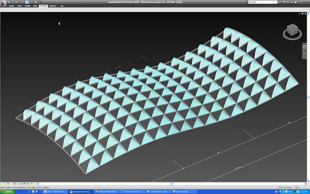 Links to these models are at the end of this post. This movie shows me creating the panel and applying it to the curvy surface:
By paramerizing the hieght and angle of the shade, i can then study how much light is allowed to pass through, and adjust the design to optimize shading based upon orientation.
Links to these models:
Source: bimtroublemaker.blogspot.com
 06:27
06:27 Unknown
 Revit Arch
 No comments
Recently I have been following David Light's blog. He is having this complex curtain wall that he briefly describe on how he do it. The following is a more detail version of it.
1. Create a new generic family. In this case, I am assuming my curtain panel to be 1000mm x 1000mm. Go to front view and create all the necessary reference planes as shown. Then use Spline to draw the path. Add the control points as necessary. The extra control points will make the curvature end at the top end bottom in a tangential manner.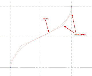
2. Draw the profile as shown at the end of the path.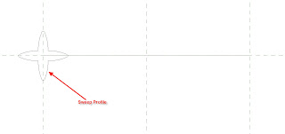
3. Goto Solid Form and choose Solid Sweep. Pick the path as shown.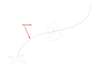
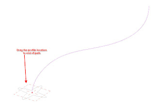
4. Drag the Profile location to the end of the path.
5. Pick on Profile and choose the profile as shown.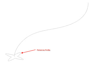
6. Choose Finish Sweep and mirror the created sweep.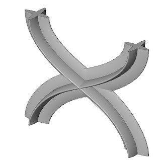
7. Saved the generic model and loaded into a new curtain panel family. Placed the generic sweep with Left Reference as origin. This is so that the cutain panel will be placed properly.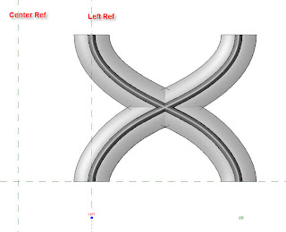
8. Create a new curtain wall with the grid spacing of 1000mm x 1000mm. Replaced all the curtain panel with the new custom panel.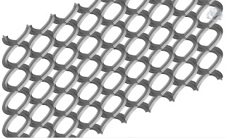
1. Create a new generic family. In this case, I am assuming my curtain panel to be 1000mm x 1000mm. Go to front view and create all the necessary reference planes as shown. Then use Spline to draw the path. Add the control points as necessary. The extra control points will make the curvature end at the top end bottom in a tangential manner.

2. Draw the profile as shown at the end of the path.

3. Goto Solid Form and choose Solid Sweep. Pick the path as shown.

4. Drag the Profile location to the end of the path.

5. Pick on Profile and choose the profile as shown.

6. Choose Finish Sweep and mirror the created sweep.

7. Saved the generic model and loaded into a new curtain panel family. Placed the generic sweep with Left Reference as origin. This is so that the cutain panel will be placed properly.

8. Create a new curtain wall with the grid spacing of 1000mm x 1000mm. Replaced all the curtain panel with the new custom panel.

Source: revitbimmer.blogspot.com.
Đăng ký:
Nhận xét (Atom)


